Description
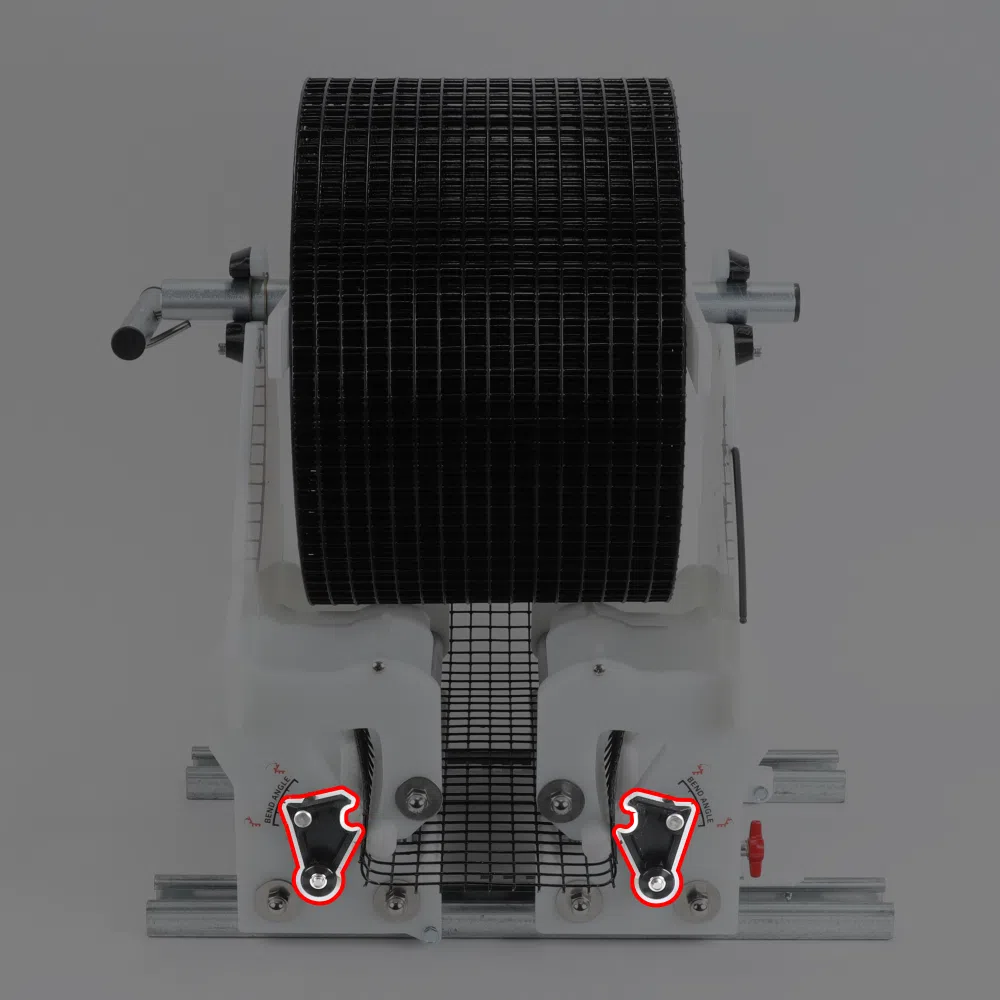
One pair of angle adjust arms and associated hardware, which allow adjustment of the wire mesh bend angle. All required hardware included. Fits AG Bender 7.0 and up. Click here for help identifying your AG Bender model.
Assembly Instructions
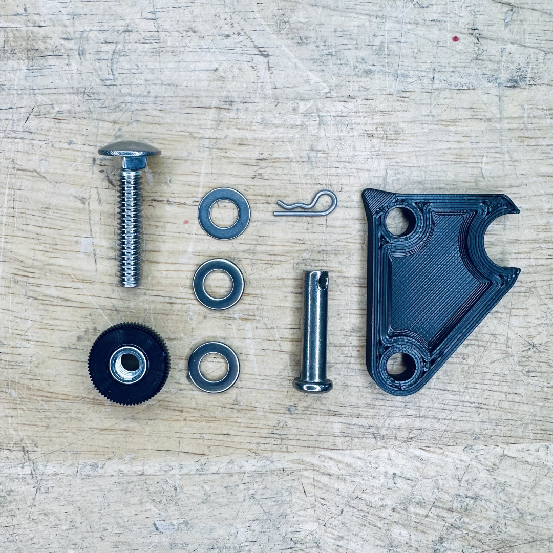
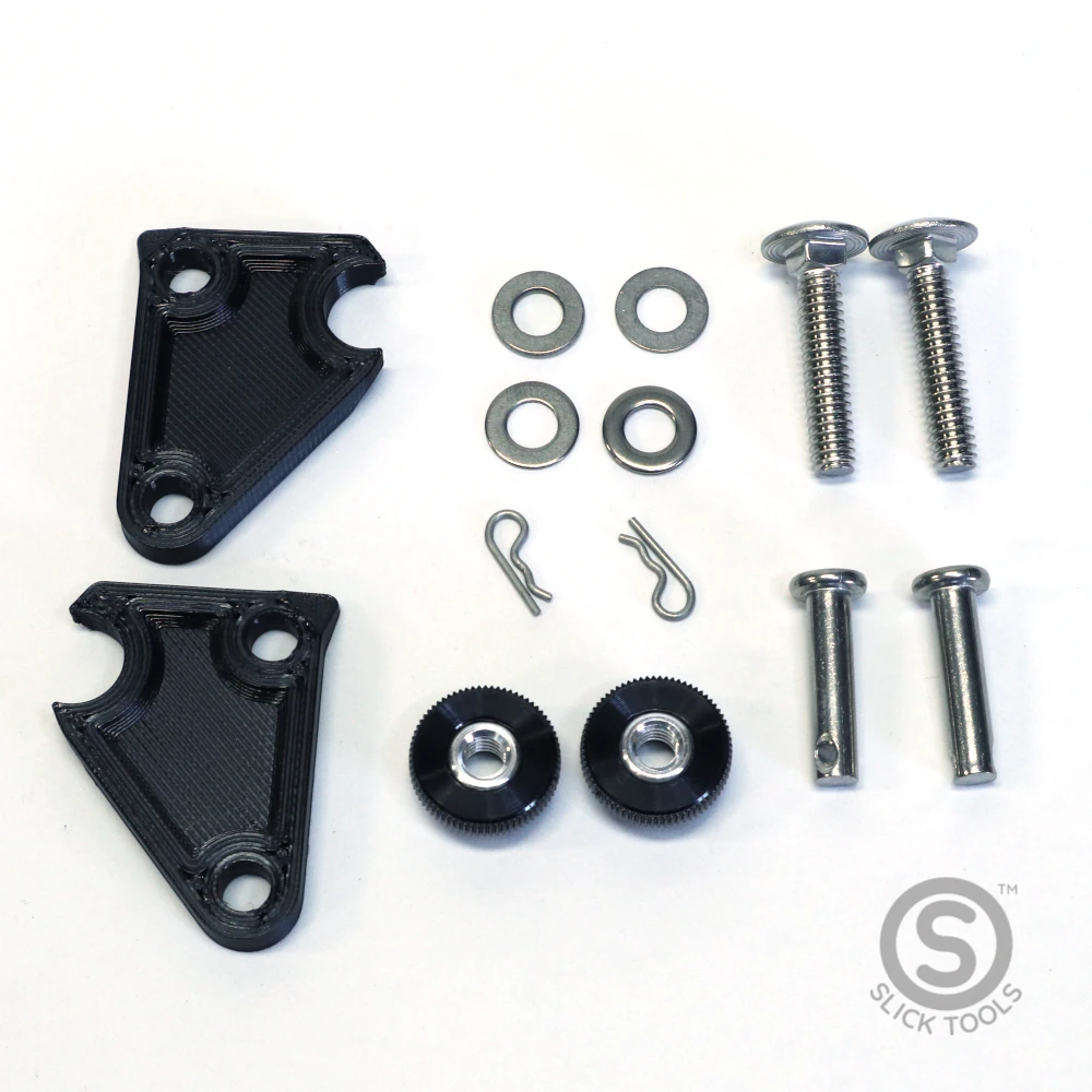
Step 1: Gather your fasteners and parts
- You were supplied enough parts to replace both sides of your AG Bender. These instructions are the same for both sides.
- 2x carriage bolts
- 2x Thumb screws
- 4x Thick washers
- 2x thin washers
- 2x Clevis pins
- 2x Cotter pins
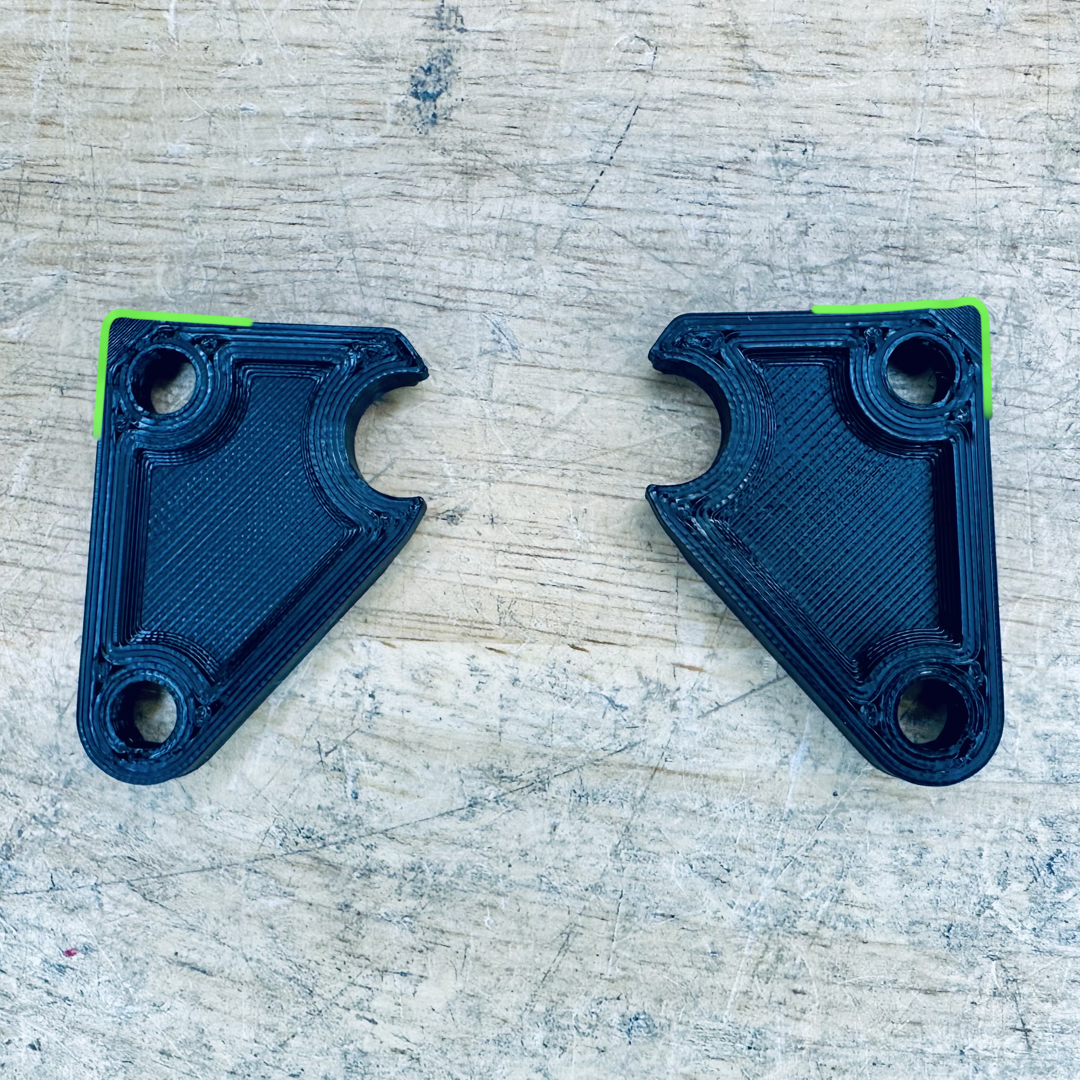
- 2x Angle adjust arms
- Gather your fasteners for the side you are servicing.
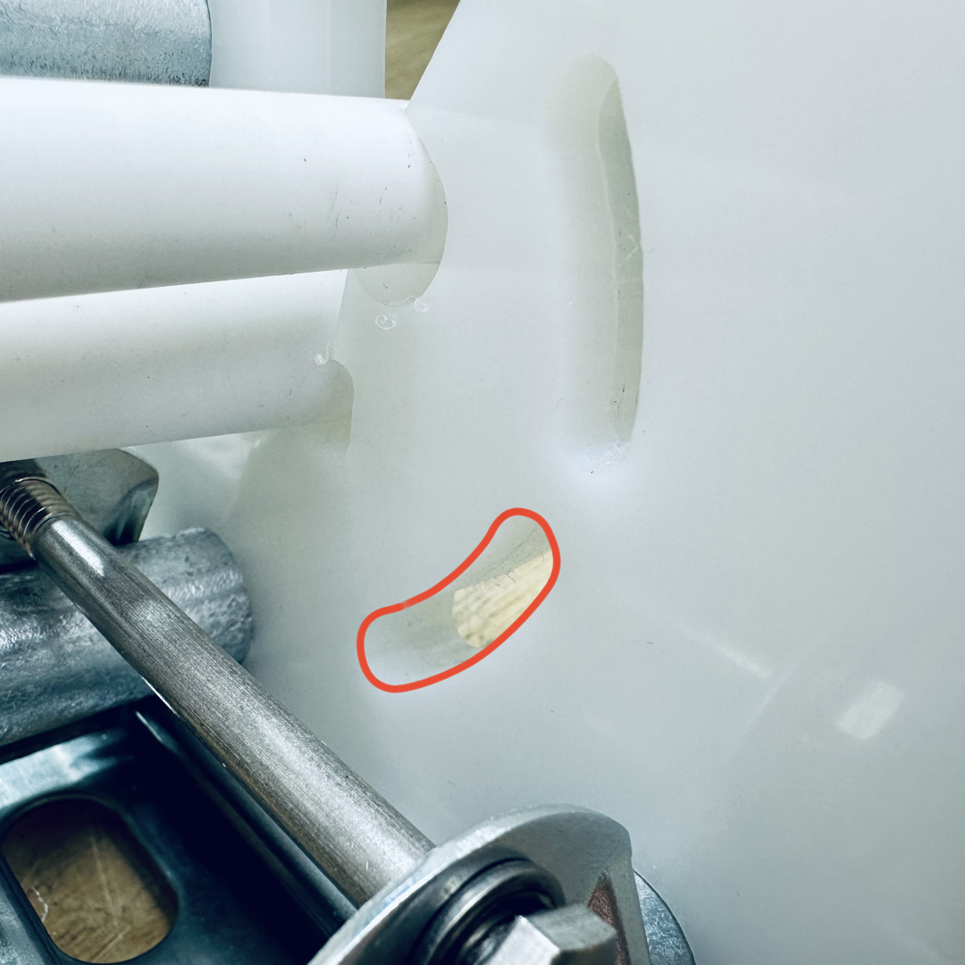
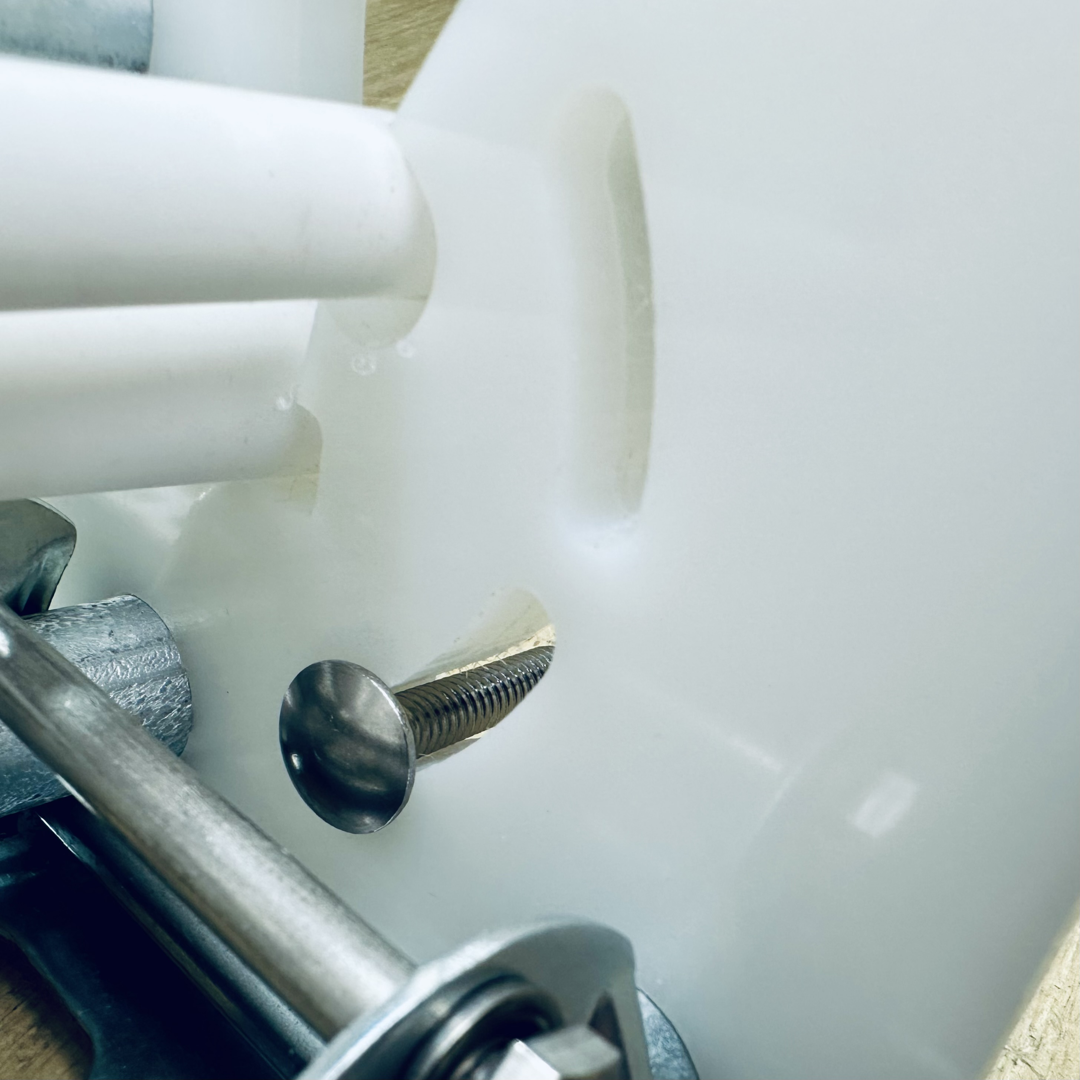
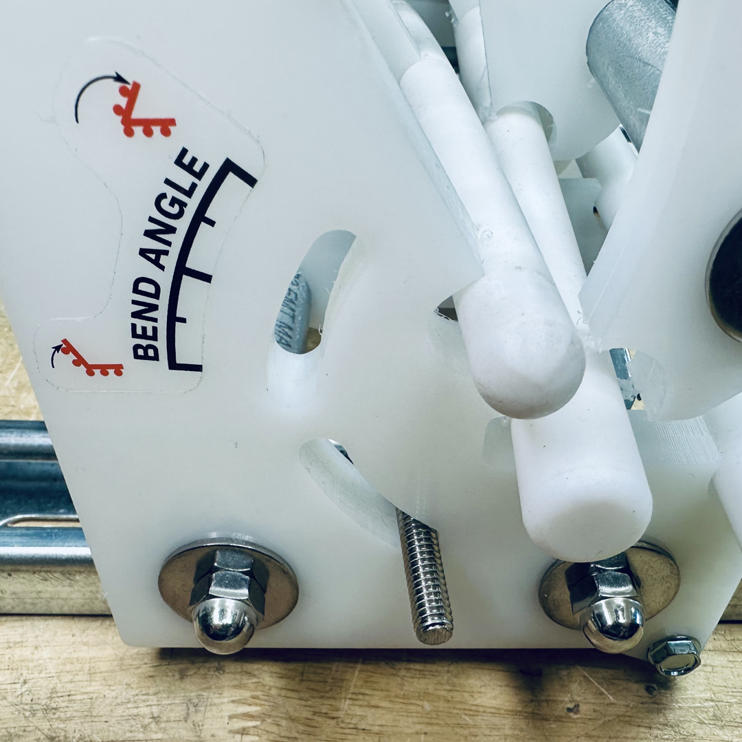
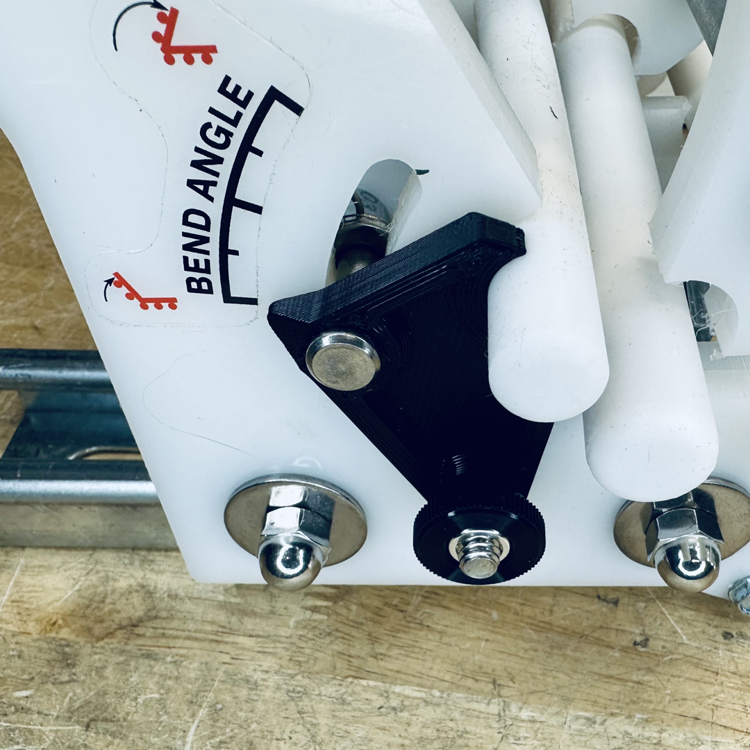
- Locate the lower slot on the back side of the angle adjust plate and insert the carriage bolt into that slot.
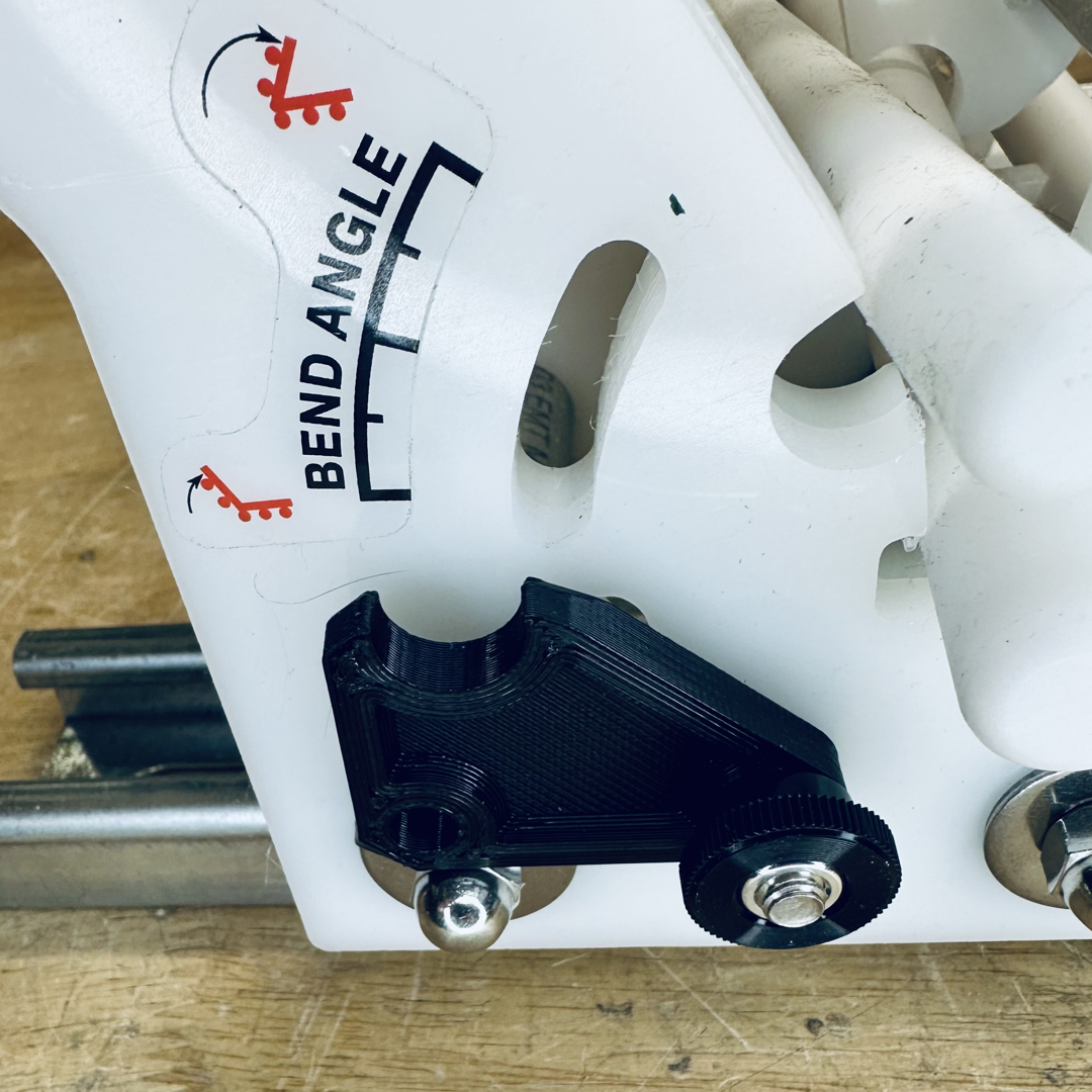
Step 2: Angle Adjust Arm
- Note that the arms are mirrored and need to be on the correct side of the AG Bender. The textured side mates against the angle adjust arm plate with the point designating bend angle
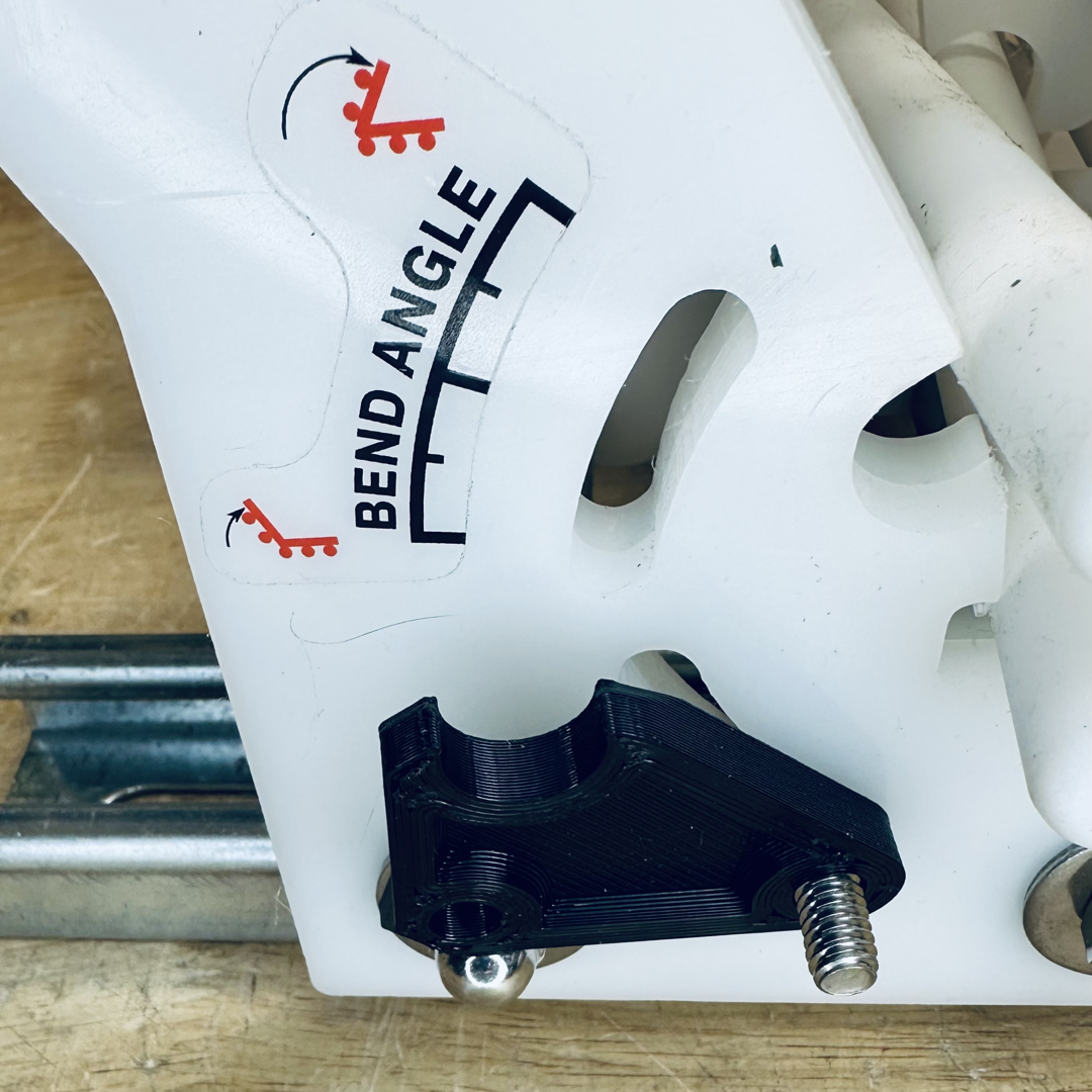
- Place the appropriate side angle adjust arm onto the carriage bolt through the arm’s bottom hole.
- Loosely thread the thumb screw onto the end of the carriage bolt. The carriage bolt needs to rest inside the slot to prevent it from rotating.
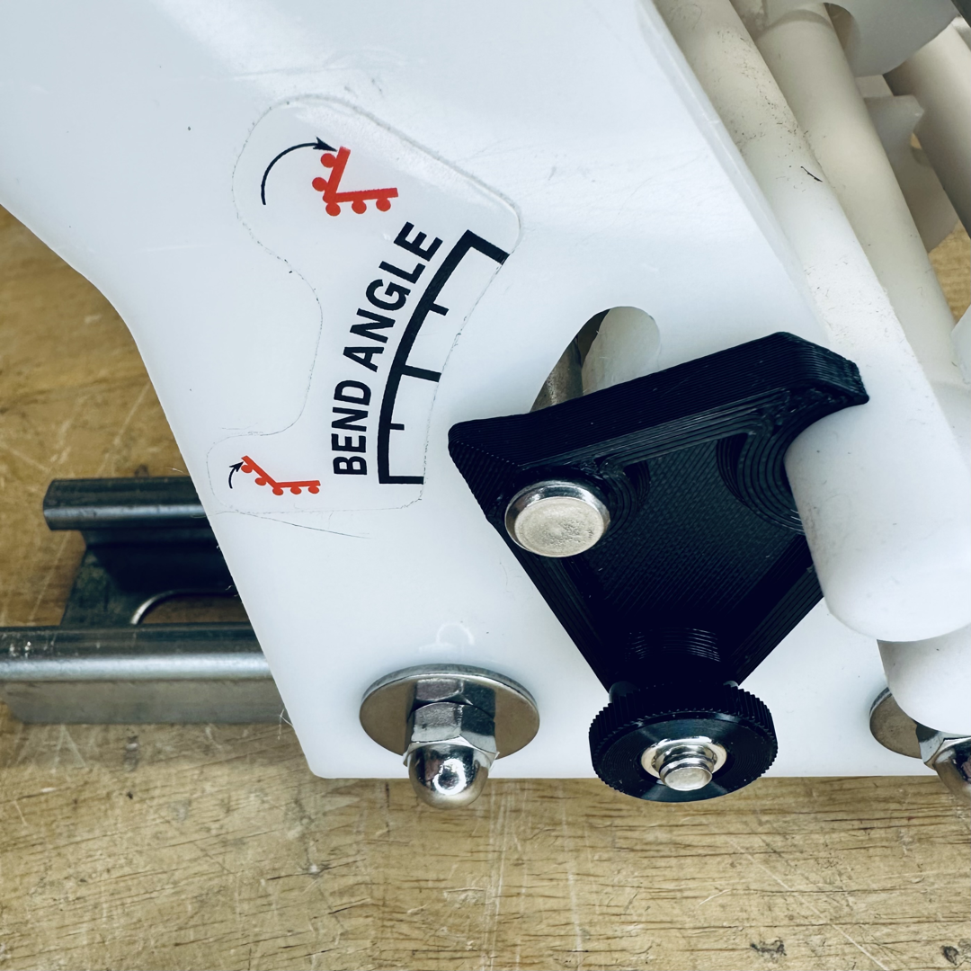
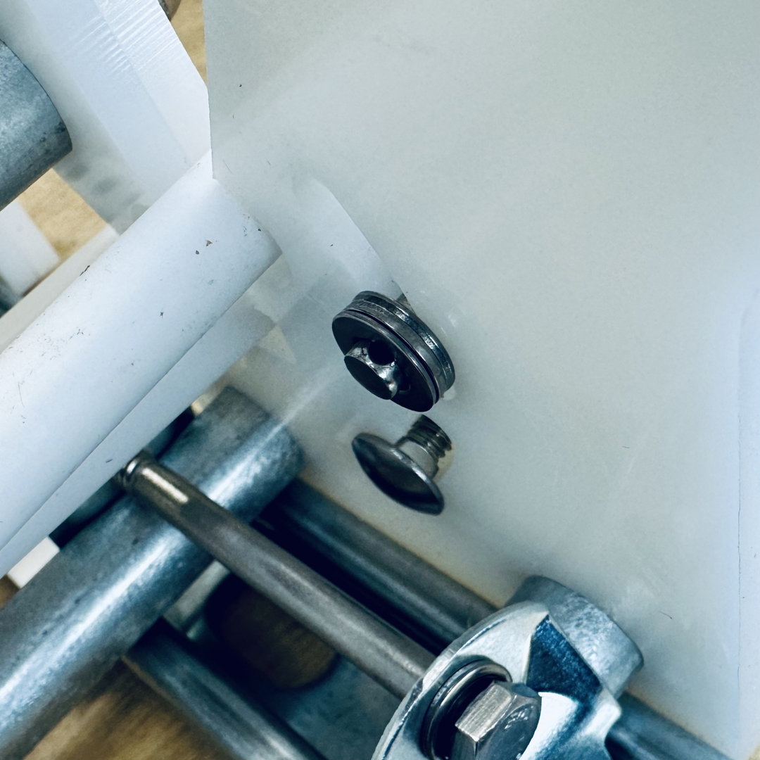
Step 3: Clevis Pin
- Place the clevis pin into the upper hole of the arm and through the upper slot on the angle adjust arm plate
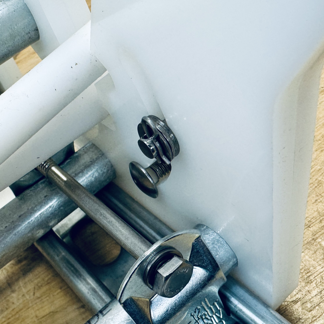
- On the backside of the plate, place the three washers you were provided.
- Snap the cotter pin through the hole on the clevis pin. This should provide some tension on this part, if necessary you may need to use one less washer if it’s too difficult to move the arm.
- The angle adjust arm needs to be able to move it’s full range of motion; check your work, tighten the thumb screw to set the angle, and you’re finished!